


Features
- High torque, low noise wet clutch and brake.
- Rigid frame with less deflection.
- High accuracy transmission gears and high rigidity crank ensure press long life and accuracy.
- Forced Lubrication system with default monitor ensures the operation reliability,
- User-friendly design and all-function electric control system enable the accessories to attach easily.
- High accuracy meets the QMS 1st level.
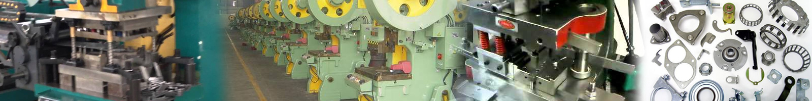
Accessories
Standard Accessories
- Hydraulic Overload Protector
- Manual Slide Adjusting Device (RX-25-45)
- Electrical Slide Adjusting
- Die Height Indicator (RX-250)
- Counter Balancers of Slide
- Rotary Com Limit Switch.
- Antirepeat Safety Device
- Magnetic Strokes Counter
- Miss feed Detector Socket.
- Pneumatic Ejector.
- Air Outlet
- Maintenance Tools.
Optional Accessories
- Power Take-off shaft.
- Pneumatic Die Cushion.
- Photoelectric Safety Device.
- Variable Speed Motor (Inverter)
- Quick Die Change Device (Q.D.C.)
- Present Counter
- Knockout Switch.
- Rubber Mount.
Specification
| Model | RX-25 S – H – P |
RX-35 S – H – P |
RX-45 S – H – P |
RX-60 S – H – P |
RX-80 S – H – P |
RX-110 S – H – P |
RX-160 S – H – P |
RX-200 S – H – P |
|||||||||||||||||||||||||||||||||||||||||||
|---|---|---|---|---|---|---|---|---|---|---|---|---|---|---|---|---|---|---|---|---|---|---|---|---|---|---|---|---|---|---|---|---|---|---|---|---|---|---|---|---|---|---|---|---|---|---|---|---|---|---|---|
| Capacity (Tonnage) | 25 | 35 | 45 | 60 | 80 | 110 | 160 | 200 | |||||||||||||||||||||||||||||||||||||||||||
| Length of Stroke (D)mm | 80 – 50 – 35 | 90 – 60 – 40 | 110 – 70 – 45 | 130 – 80 – 50 | 150 – 100 – 60 | 180 – 110 – 70 | 200 – 130 – 80 | 220 – 150 – 90 | |||||||||||||||||||||||||||||||||||||||||||
|
|||||||||||||||||||||||||||||||||||||||||||||||||||
| Tonnage Rating Point (B.D.C.)mm | 3.2 – 3.2 – 2.3 | 3.2 – 3.2 – 2.3 | 3.2 – 3.2 – 2.3 | 4 – 4 – 2.3 | 5 – 5 – 3.2 | 5 – 5 – 3.2 | 6 – 6 – 4 | 6 – 6 – 4 | |||||||||||||||||||||||||||||||||||||||||||
| Die Height (D.H)mm | 230 – 200 – 200 | 250 – 220 – 220 | 270 – 240 – 240 | 300 – 270 – 270 | 330 – 300 – 300 | 350 – 320 – 320 | 400 – 360 – 360 | 450 – 400 – 400 | |||||||||||||||||||||||||||||||||||||||||||
| Adjustment of Slide(G)mm | 50 | 50 | 60 | 70 | 80 | 90 | 100 | 110 | |||||||||||||||||||||||||||||||||||||||||||
| Area of Slide(PxQ)mm | 330 x 250 | 380 x 300 | 430 x 350 | 480 x 400 | 560 x 460 | 650 x 520 | 720 x 580 | 860 x 650 | |||||||||||||||||||||||||||||||||||||||||||
| Diameter of Shank Hole mm | Ø38.1 | Ø50.8 | Ø50.8 | Ø50.8 | Ø50.8 | Ø50.8 | Ø65 | Ø65 | |||||||||||||||||||||||||||||||||||||||||||
| Area of Bolster (ExF)mm | 700 x 320 | 780 x 400 | 840 x 440 | 900 x 520 | 1050 x 600 | 1150 x 680 | 1250 x 760 | 1400 x 840 | |||||||||||||||||||||||||||||||||||||||||||
| Thickness of Bolster (T)mm | 85 | 100 | 115 | 130 | 140 | 155 | 165 | 180 | |||||||||||||||||||||||||||||||||||||||||||
| Height of Bolster (Z)mm | 800 | 800 | 800 | 900 | 900 | 900 | 900 | 1000 | |||||||||||||||||||||||||||||||||||||||||||
| Inside Measurement frame (R)mm | 394 | 490 | 516 | 544 | 610 | 670 | 730 | 900 | |||||||||||||||||||||||||||||||||||||||||||
| Motor Floor Side Adjustment HPxP | – | – | – | 0.5 x 4 | 0.5 x 4 | 0.5 x 4 | 1 x 4 | 1 x 4 | |||||||||||||||||||||||||||||||||||||||||||
| Foot Size (AxB)mm | 750 x 1058 | 830 x 1125 | 890 x 1210 | 940 x 1315 | 1050 x 1480 | 1160 x 1680 | 1300 x 1985 | 1480 x 2113 | |||||||||||||||||||||||||||||||||||||||||||
|
|||||||||||||||||||||||||||||||||||||||||||||||||||
| Moter for side Adjustment (HP x P) | – | – | – | 0.5 x 4 | 0.5 x 4 | 0.5 x 4 | 1 x 4 | 1 x 4 | |||||||||||||||||||||||||||||||||||||||||||
| Foot size (A x B)m.m. | 750 x 1058 | 830 x 1125 | 890 x 1210 | 940 x 1315 | 1050 x 1480 | 1160 x 1680 | 1300 x 1985 | 1480 x 2113 | |||||||||||||||||||||||||||||||||||||||||||
| Position of Anchor Bolts(MxN)mm | 620 x 860 | 730 x 925 | 790 x 1010 | 840 x 1115 | 950 x 1230 | 1060 x 1380 | 1180 x 1655 | 1360 x 1755 | |||||||||||||||||||||||||||||||||||||||||||
| Accuracy | CNS 1st | CNS 1st | CNS 1st | CNS 1st | CNS 1st | CNS 1st | CNS 1st | CNS 1st | |||||||||||||||||||||||||||||||||||||||||||
| Die Cushion (Optional) | |||||||||||||||||||||||||||||||||||||||||||||||||||
| Capacity (Tonnage) | 2.2 | 2.2 | 3.5 | 3.5 | 6 | 8 | 10 | 14 | |||||||||||||||||||||||||||||||||||||||||||
| Length of Stroke (mm) | 50 | 50 | 70 | 70 | 80 | 90 | 100 | 110 | |||||||||||||||||||||||||||||||||||||||||||
| Area of Pad (mm) | 300 x 210 | 300 x 210 | 340 x 234 | 340 x 234 | 410 x 260 | 480 x 320 | 540 x 340 | 640 x 440 | |||||||||||||||||||||||||||||||||||||||||||
Material & Specifications are subject to change without prior notice.
* All dimensions are in mm


